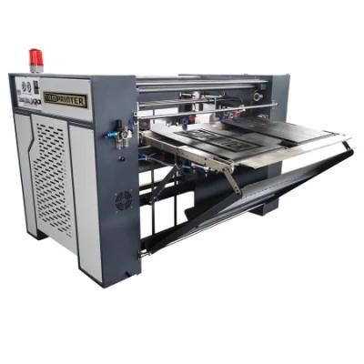
Automatic Stack Paper Feeding Machine
Shenzhen Tamprinter Printing Machinery Co., Ltd.- Max H of Stacking Paper:650mm
- Max. Paper Dimension:800X600mm
- Min. Paper Dimension:350X250mm
- Top Speed:4200p,H 0~55m,Min
- Overall Size:L183 × W138 × H125cm
- Transport Package:Plywood Case,Wooden Case,Carton,as Required
Base Info
- Model NO.:TM-JB-800S
- Specification:CE; ISO9001-2000
- Trademark:Tamprinter
- Origin:China(Mainland)
- HS Code:8419399090
- Production Capacity:100 Sets,Month
Description
full automatic stacker can be used with full automatic screen press, UV machine or UV/IR dryer together, used to collect paper and make the paper in order automatically and enhance productive efficiency & product quality.
1. Collecting the paper and making the paper in order automatically.
2. Fit for all kinds of paper size, adjusted equipment in back, left and right side can be operated easily and conveniently
3. Photoelectric equipment inspects and controls boards, the pneumatic organ make the paper in order.
4. The induction equipment controls the paper holding board decline, and ensure the paper collecting automatically and glibly.
5. The paper feeding system is controlled by frequency conversion, stepless turning.
Automatic offset printing machine, automatic roller screen printing machine, automatic stop rotary partial screen printing machine, and one of the supporting equipment of other automatic paper printing production lines, complete the printing of finished products or semi-finished products, which can greatly improve production Efficiency and quality.
The whole machine can be divided into several parts such as the paper feeding frame mechanism, the whole paper mechanism, the paper delivery table lifting mechanism and the electrical control system.
1. The paper feeder mechanism is composed of two parts, one is the conveyor belt part, which adopts frequency conversion speed regulation, which can easily adjust the conveyor belt speed to control the paper conveying speed, so as to adapt to different printing speeds. The other part is the air blowing device. When the paper is separated from the conveyor belt, the air flow blows out from the air blowing pipe, holding the paper up and moving it forward for a certain distance, then the air flow is turned off, and the paper falls onto the delivery table.
2. The whole paper part adopts a pneumatic paper arranging mechanism. The pneumatic structure has low working noise, stable and reliable action, and the adjustment of the cylinder position is convenient and adjustable to suit different sizes of paper or printed matter.
3. The lifting and lowering of the delivery table is driven by an electromagnetic brake motor and four synchronous motion chains, which can accurately stop at the required height and at the same time ensure the level of the delivery table.
4. The electrical control part is simple and practical, with optional PLC program control, easy to operate, safe and reliable.
The utility model provides a palletizer and an automatic paper take-up machine, and relates to the technical field of paper take-up machines. The palletizer includes a base, a transmission and conveying mechanism, a lifting mechanism and a collection mechanism. The transmission mechanism includes a transmission frame, a transmission motor, a driving roller and a driven roller; the conveying mechanism is connected with a guide wheel and a photoelectric sensor. The conveyor belt and guide wheels on the palletizer can roll and guide the conveying of packaging paper, reducing the occurrence of packaging paper wrinkles or paper jams. The photoelectric sensor on the conveying mechanism transmits signals to make the lifting motor and the collecting cylinder move synchronously. The whole process does not stall until a pallet pallet is filled with a height of 65cm. The forklift removes it and replaces it with a new pallet, and so on.
The lifting mechanism includes a lifting platform, a lifting motor, a gear transmission structure and a support frame; the collection mechanism includes a side baffle, a rotating support plate and a collection cylinder. The patented technology of the utility model is a printing paper automatic receiving and palletizing device with ingenious design, reasonable structure, convenient use and strong practicability. This device has a high degree of automation and can improve work efficiency and reduce the labor cost of the enterprise after use, especially Suitable for continuous mass production.
[Summary of technical implementation steps]
The technology relates to the field of mechanical equipment, in particular to a printing carton automatic receiving and palletizing device.
Technology Introduction
At present, the cartons need to go through multiple processes such as printing, slotting, and collection during the processing. At present, the collection and palletizing process is done manually. Usually, workers collect the processed cartons at the discharge end and move them to the side for stacking. Neat, the defects of this method are: 1. The speed is slow, the efficiency is low, multiple workers are required to operate, and the labor cost is high. 2. The staff is labor intensive. 3. The palletizing is not neat.
Technical realization ideas
The purpose of this technology is to make up for the shortcomings of the prior art and provide a printing carton automatic receiving and palletizing device that can improve production efficiency and reduce labor intensity. The purpose of this technology is achieved through the following technical means: A printing carton automatic receiving and palletizing device, which is characterized by: comprising a base, a transmission mechanism, a lifting mechanism and a collection mechanism. The transmission mechanism includes a transmission frame, a transmission motor, a driving roller and The driven roller, the transmission motor is installed on the base, and the transmission motor is connected to and drives the driving roller, the driving roller is installed on the right side of the transmission frame, and the driven roller is installed on the left side of the transmission frame. The driving roller and the driven roller adopt Belt connection, the right side of the transmission frame is installed on the base, and the left side of the transmission frame is connected to the lifting mechanism; the lifting mechanism includes a lifting platform, a lifting motor, a gear transmission structure and a support frame, and a support frame is installed on the left side of the base. Two vertical beams and one cross beam are formed. The cross beam is installed between the two vertical beams. The lifting motor is installed on the cross beam. The lifting motor is connected to the lifting platform through a gear transmission structure. The lifting platform is located between the two vertical beams and the lifting platform is connected to the The left side of the transmission frame is connected; the collection mechanism includes a side baffle, a rotating pallet and a collection cylinder. The side baffle is installed on the left side of the lifting platform and has a gap with the lifting platform to form a carton collection area. A rotating pallet is arranged under the platform, and the two rotating pallets are respectively connected with the side baffle plate and the lifting platform through a collecting cylinder. Moreover, an auxiliary frame is hinged on the right side of the base through an auxiliary cylinder. The advantages and positive effects of this technology are: 1. This device is mainly composed of a base, a transmission mechanism, a lifting mechanism and a collection mechanism,...
Technical protection point
An automatic receiving and palletizing device for printing cartons, which is characterized in that it includes a base, a transmission mechanism, a lifting mechanism, and a collection mechanism. The transmission mechanism includes a transmission frame, a transmission motor, a driving roller and a driven roller. The transmission motor is installed on the base, and The drive motor is connected to and drives the driving roller. The driving roller is installed on the right side of the transmission frame. The left side of the transmission frame is equipped with a driven roller. The driving roller and the driven roller are connected by a belt. The right side of the transmission frame is installed on the base. , The left side of the transmission frame is connected with the lifting mechanism; the lifting mechanism includes a lifting platform, a lifting motor, a gear transmission structure and a support frame. The left side of the base is equipped with a support frame. The support frame is composed of two vertical beams and a cross beam. Between the two vertical beams, the lifting motor is installed on the cross beam. The lifting motor is connected to the lifting platform through a gear transmission structure. The lifting platform is located between the two vertical beams, and the lifting platform is connected to the left side of the transmission frame; the collection mechanism includes a side stop. The side baffle is installed on the left side of the lifting platform and there is a gap between the lifting platform to form a carton collection area. A rotating pallet is installed under the side baffle and the lifting platform. The two The two rotating pallets are respectively connected with the side baffle plate and the lifting platform through the collecting cylinder.
